
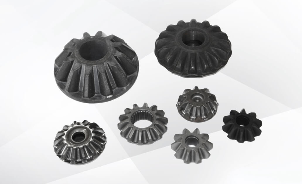
Bevel gears, most notably used in automotive differential gears, continue to evolve alongside the rapid transition toward electrification and higher power outputs. However, manufacturing facilities today face numerous challenges, including historic surges in material and electricity costs, as well as dimensional distortion during post-forging heat treatment.
This article provides an in-depth explanation of the advantages of cold closed-die forging—a manufacturing method capable of overcoming these modern cost and environmental challenges. We will also introduce Yamanaka Eng’s precise approach to preventing mass-production issues, utilizing a streamlined development process driven by CAE analysis and our proprietary “high-precision tooth profile compensation” technology.
What is a Bevel Gear? Why Forging is Dominant and Recent Market Trends
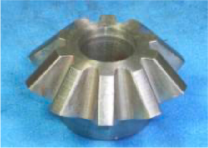
A bevel gear is a cone-shaped gear with teeth cut along its conical surface, used to transmit power between two intersecting axes. It is an indispensable mechanism for changing the direction of torque by 90 degrees, heavily utilized in automotive differential gears, agricultural machinery, and the drive units of industrial robots.
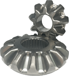
Because of its complex three-dimensional geometry, cutting the teeth one by one via conventional machining results in massive material waste and long processing times. For this reason, bevel gears are inherently prime candidates for forging and have long been one of the most widely adopted forged components in mass-production environments.
However, with the ongoing transformation of powertrains in the automotive sector, the development environment and technological trends surrounding bevel gears are undergoing massive shifts:
Surge in New Component Development and Prototyping:
As powertrains are reinvented, new gear development projects are rapidly multiplying. Setting up these next-generation lines requires highly accurate prototyping, leading to a substantial increase in technical consultations and prototyping requests at Yamanaka Eng.
The Dilemma of Upsizing (Shifting from Hot/Warm to Cold Forging):
To handle the high torque of electric motors and high-output units, bevel gears are trending toward larger sizes. Traditionally, large gears were formed using warm or hot forging to soften the material, followed by cold sizing to ensure precision. However, achieving carbon neutrality while managing historic surges in electricity and material costs has become critical. Hot and warm forging require massive amounts of energy to heat materials, creating cost and environmental risks. Consequently, there is a rapid surge in demand for shifting from warm/hot forging to cold closed-die forging, which eliminates flash entirely and pushes material yield to the absolute limit.
Industry-Wide Trend: Active Investment in Warm and Hot Closed-Die Forging:
Looking beyond bevel gears, conventional hot forging with flash hits manufacturers with a double penalty of material loss and soaring electricity bills. As a result, more companies are investing in process conversions to hot closed-die forging to utilize 100% of the raw material. Additionally, to shave even a few degrees off the setting temperature and reduce electricity costs, the movement to shift from hot to warm forging is accelerating across the industry.
Technical Overview: How “Cold Closed-Die Forging” Eases the Burden of Energy and Material Costs
Let’s look at why cold closed-die forging successfully breaks through these cost and environmental barriers by examining the differences from flash-generating forging and the core essentials of die design.
Differences Between Conventional Flash Forging and Closed-Die Forging
The most critical difference lies in whether excess material—known as flash—is allowed to escape during the process.
| Evaluation Item | Conventional Flash Forging | Cold Closed-Die Forging |
|---|---|---|
| Material Yield | Approx. 5% to 10% loss generated as flash. | Nearly 100% (No flash on the outer periphery). |
| Material Weight & Power Consumption | Increased by the volume of the flash. | Kept to the absolute minimum. |
| Post-Processing | Trimming or secondary machining is indispensable. | No trimming required; secondary machining allowance is minimized. |
| Dimensional Accuracy | High variance due to thickness changes and trimming. | Excellent die replication and high precision. |
Challenging 100% Yield to Reduce Material Cost Pressures:
Conventional forging allows material to squeeze out through die gaps as “flash” to ensure the die cavity fills completely. This flash is later trimmed off and scrapped, creating a substantial material loss. In contrast, closed-die forging traps a volume of material identical to the finished product inside a completely sealed die cavity, distributing the metal flawlessly with zero flash. This achieves nearly 100% material yield on the outer periphery (excluding the center ID piercing), lowering raw material costs.
The Power Savings Difference in Material Weight Heating:
Power consumption during heating scales directly with the weight of the material being processed. Heating occurs during forging in hot processes, and during pre-heat treatment (annealing) in cold processes. Because flashless cold closed-die forging minimizes the initial material weight, it reduces the total energy required for heating.
The Critical Importance of Die Design in Cold Closed-Die Bevel Gear Forging
Despite these enormous benefits, applying cold closed-die forging to complex shapes like bevel gears was historically difficult due to one major obstacle: extreme die stress.
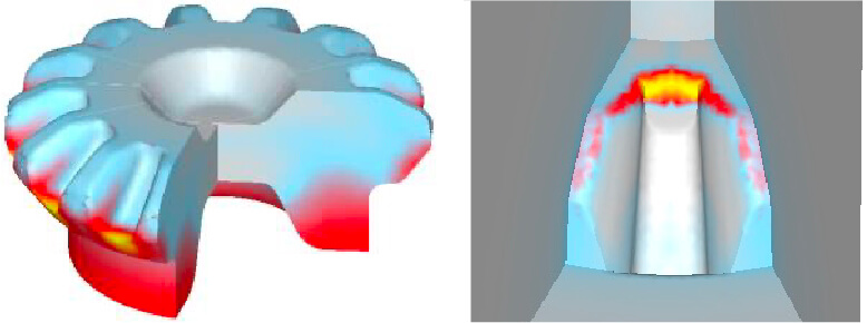
Compressing cold, hard material inside a sealed environment with no flash escape route subjects the die internals to pressures several to tens of times higher than hot forging. Bevel gear teeth feature sharp, alternating profiles where stress easily concentrates. If the die design is inadequate, the tooling risks premature failure or cracking within just a few shots.
Securing a tool life robust enough for mass production requires highly advanced die design engineering:
High-Density Die Structure Design:
For a die trying to burst outward from internal pressure, the design of the stress rings (reinforcement rings) used to pre-compress the die externally is paramount. Interference fit ratios and multi-layer ring configurations must be calculated logically. It is also crucial to maximize the fillet radii (R) of the forged part geometry to eliminate stress concentration points and select optimum die materials capable of withstanding extreme internal pressures.
Material Flow Control and “Deformation Layout”:
By predicting exactly where and when pressure will peak inside the die cavity, we optimize punch geometries and the initial blank shape. The key is designing for minimum optimal filling—preventing material from crowding unnecessary areas. By controlling the filling sequence and subsequent material flow, we ensure the gear teeth fill completely to their tips while venting local peak pressures that shorten tool life.
Managing Closed-Die Clamping Force:
Since upper and lower dies must remain sealed while material fills the cavity, calculating and engineering the proper clamping force to keep the dies from separating under intense internal pressure is absolutely vital.
Yamanaka Eng’s Bevel Gear Forging Development Process
While cold closed-die forging offers immense benefits, manufacturers must conquer two major bottlenecks: extreme die loads and heat treatment distortion in post-processing.
The competitive edge in modern bevel gear development does not come from simply machining a die to a print; it comes from engineering foresight that accounts for mass-production loads and calculating final product accuracy through post-processing.
Yamanaka Eng handles everything from die design and prototyping to post-heat treatment precision verification entirely in-house. Our seamless 4-step process ensures a reliable launch without costly backtracking:
Step 1: 3D Alignment of the Target via Master Gear
We never initiate development based purely on 2D drawings. We always establish and share a “Master Gear” (the target shape) using 3D models or physical samples with our customers to align our final goals perfectly.
Step 2: Virtual Validation via CAE Analysis
Using the shared Master Gear as our baseline, we design the tooling and conduct rigorous material flow and die-stress simulations using the plastic deformation software DEFORM. By visualizing how material fills the bevel gear teeth and meticulously simulating the process, we identify the ideal sequence and timing for compression. This eliminates risks such as underfilling, part defects, or premature die failure before steel is cut, establishing forming parameters that balance part quality with extended tool life.
Step 3: Prototyping, Heat Treatment, and Cycle Measurement
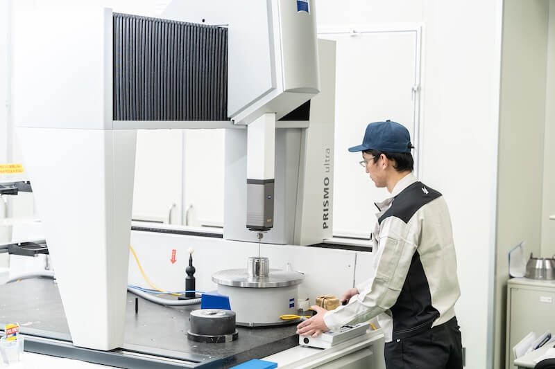
Once the dies are fabricated, we perform initial prototyping in-house and measure the forged tooth profiles using high-performance coordinate measuring machines (CMM). Next, to replicate actual mass production, the customer performs secondary machining (such as ID turning) and carburizing heat treatment. Because heat treatment inevitably induces thermal distortion, the parts are sent back to us for another round of high-precision tooth profile measurements.
Step 4: Tooth Contact Evaluation and Precision Compensation
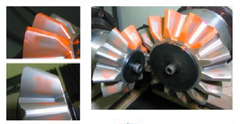
Using the returned physical parts, we test and evaluate gear-meshing accuracy on our in-house gear-meshing testers. This ability to evaluate ideal tooth contact under conditions that replicate actual machinery allows us to verify part precision seamlessly under one roof. Because extreme forming loads cause elastic deformation in the dies and material spring-back—both of which reduce profile replication accuracy—the die geometry must be compensated. We apply proprietary compensation technologies derived from precise tracking of shape changes across forging, machining, and heat treatment to achieve perfect final product accuracy.
Recommendation for Set Development
While we can develop individual bevel gears, we highly recommend developing the meshing pair (mating gears) as a set. Evaluating them together ensures the ideal tooth contact required for the actual machine can be engineered perfectly into both parts.
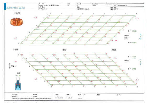
Comprehensive 81-Point Contact Checking (9×9 Grid)
We establish a 9×9 grid totaling 81 measurement points per tooth to check deviations against the Master Gear baseline. Thanks to this ultra-precise feedback loop, we have achieved cases where all 81 points fell within a 10-micron (0.01mm) tolerance window on the very first prototyping trial.
The Advantages of Virtual Tooth Contact Analysis
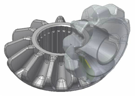
Before running physical tests, we can pre-verify gears using virtual tooth contact simulations. Our records show that virtual contact results match physical test results with high accuracy. We highly recommend utilizing virtual analysis to reduce prototype iterations and maximize the reliability of your Master Gear.
Preventing Mass-Production Troubles: Yamanaka Eng’s Strengths and Stance on “Right-First-Time” Quality
When launching a forged bevel gear project, our approach goes beyond delivering a die built to print. We collaborate closely with our customers to control variances in heat treatment and post-processing. When this collaboration is aligned, we achieve right-first-time quality on the initial trial—or at latest by the second prototype—in the vast majority of projects.
Engineering Proposals for “Tolerance Relaxation” Aimed at Mass Production
Modifying part geometries after mass production has commenced is exceptionally costly and logistically difficult.
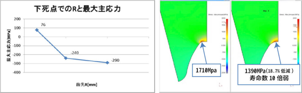
One of the leading causes of bevel gear die failure is cracking due to stress concentrations in the sharp corners (fillet R) of the tooling. Tool designers naturally want to maximize this radius to extend tool life. Conversely, gear application engineers want to minimize this radius (approaching a sharp edge) to increase the gear’s total meshing ratio and performance.
To bridge these contradictory goals, Yamanaka Eng utilizes CAE to logically determine the optimal radius value that maximizes tool life while fully guaranteeing gear quality and meshing performance.
Example Analysis Output:
If the tooth tip radius drops below a specific threshold, stress increases exponentially, escalating failure risks. Identifying the optimal radius balance is crucial.
Based on this objective data, we frequently propose specification optimization (tolerance relaxation) to slightly enlarge the tooth tip radius compared to conventional designs. When customers integrate this optimization into their differential gear durability testing, they successfully launch mass-production lines characterized by high stability, minimized running costs, and an exceptional absence of die-cracking disruptions.
The ability to look ahead at mass-production risks and preemptively deliver simulation-backed design proposals is precisely why manufacturers choose Yamanaka Eng.
Bevel Gear Forging Track Record & Case Studies
Our advanced forging technologies support manufacturing excellence across multiple industries, led by the automotive sector. Here are some representative examples from our development and manufacturing achievements:
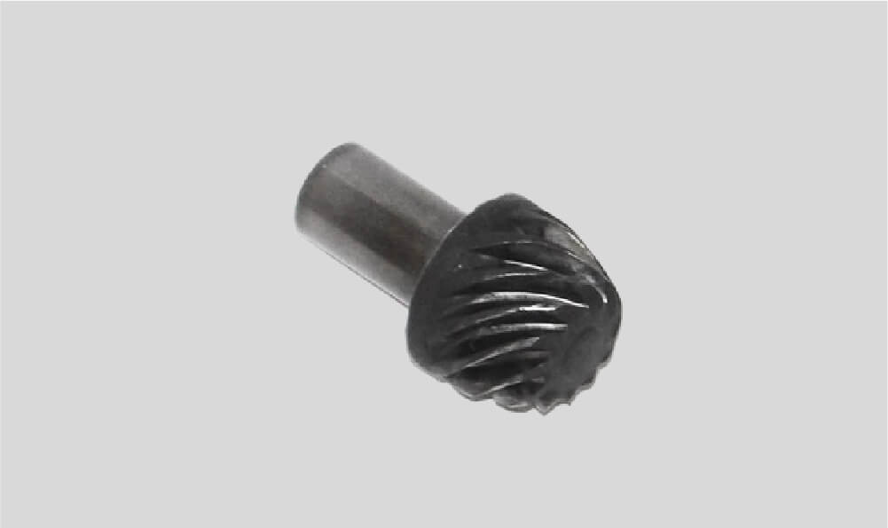
Spiral Bevel Gear
Method:Extrusion
Material:SCM420
Number of Stations:1 Step
Forming Tonnage:120ton
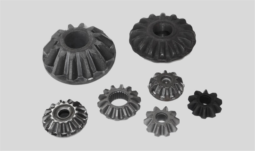
Bevel Gear
Method:Cold Enclosed Forging
Material:SCr420
Number of Stations:2-5 Steps
Forming Tonnage:700ton
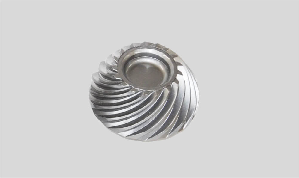
Spiral Bevel Gear
Method:Cold Enclosed Forging
Material:SCr420
Number of Stations:1 shot
Forming Tonnage:1200ton

Bevel Gear with Serrationー
Method:Cold Enclosed Forging
Material:SCM420
Number of Stations:1 shot
Forming Tonnage:650ton
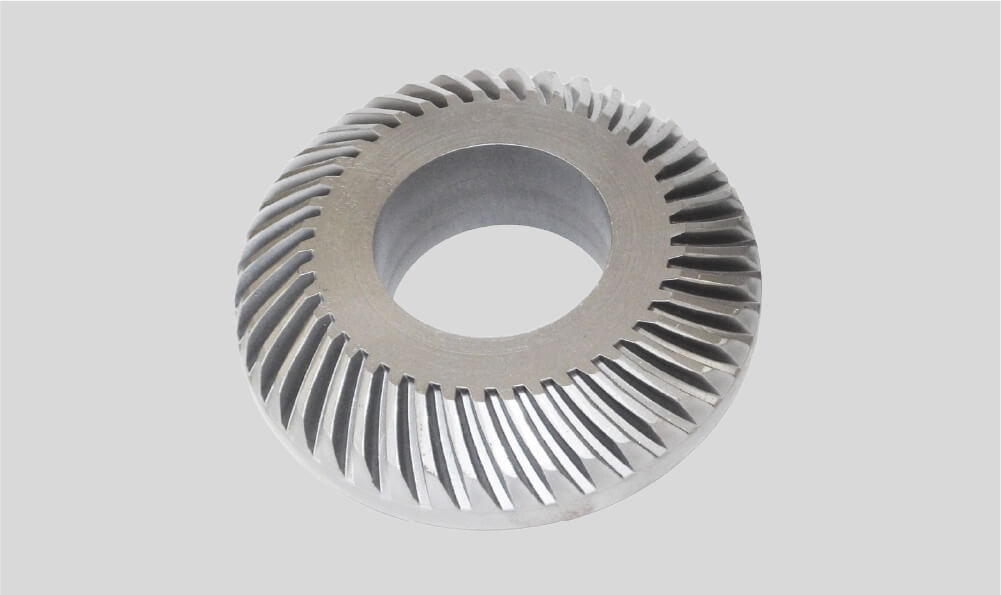
Spiral Bevel Gear
Method:Cold Enclosed Forging
Material:SCr420
Number of Stations:1 shot
Forming Tonnage:1300ton

Spiral Bevel Gear
Method:Extrusion
Material:SCM420
Number of Stations:1 Step
Forming Tonnage:210ton
For Bevel Gear Forging and Optimization, Consult Yamanaka Eng
Meeting carbon neutrality targets, cutting energy expenses, and delivering the ultra-high precision demanded by next-generation powertrains requires a holistic engineering approach. Shifting from hot/warm to cold processing and designing dies that account for heat treatment distortion are no longer optional.
- “We want to transition our current hot-forged gears to cold closed-die forging to reduce utility costs.”
- “We want to utilize virtual analysis during prototyping to launch at the lowest cost in the shortest timeframe.”
- “We need a partner to help design tough tooling and robust products that won’t suffer from die failures or mass-production variances.”
If you are a design or manufacturing engineer facing challenges with bevel gear development and mass production, leverage Yamanaka Eng’s extensive data and expertise. We provide optimal solutions from initial prototyping through stable mass production.
[Click Here for Technical Consultation & Inquiries]
Frequently Asked Questions (FAQ)
When switching from hot to cold forging, will the mechanical strength (fatigue limits, wear resistance) of the bevel gear be compromised?
No, strength will not decrease. Regardless of whether hot or cold forging is selected, both processes undergo secondary carburizing heat treatment afterward. Consequently, the mechanical strength achieved after the final heat treatment remains essentially identical.
If the mating gear (master) is unavailable during the prototyping stage, can we still consult on tooth profile compensation for just one side?
Yes, absolutely. If you can provide the engineering drawing or 3D CAD data (target geometry) of the mating gear, we can calculate backward even without the physical part. This allows us to apply high-precision tooth profile compensation directly to the die so the final assembled pair achieves ideal tooth contact.
What is the maximum size (outer diameter and module) for bevel gear forging that Yamanaka Eng can accommodate?
While the final capability depends on your available press tonnage and tooling specifications, we have a broad track record ranging from automotive differential gears up to relatively large bevel gears designed for industrial machinery. If you share your required specifications—such as outer diameter, module count, and target torque—along with your part drawings, we will evaluate feasibility and propose the optimal manufacturing plan, selecting from cold closed-die, warm, or hot forging methods.
Author Profile

H.T Director, Solution Division, Yamanaka Eng Co., Ltd.
H.T is a veteran engineer who has dedicated his entire 43-year career to the field of forging. During his long tenure at a major automotive manufacturer, he mastered every stage of the process—from die design and equipment installation to new component launches and the development of advanced forging methods. His technical expertise is highly recognized in the industry, highlighted by his prestigious receipt of the "Sokeizai Industry Technology Award" on two separate occasions.